
Per Stenebo
2019-07-13 10:07:23
2020-12-26 10:43:34

PWM power circuit
This page is deprecated, use this page instead.
External recources
Driving motors, lights, etc. from an Arduino output pin (MOSFET, PWM).
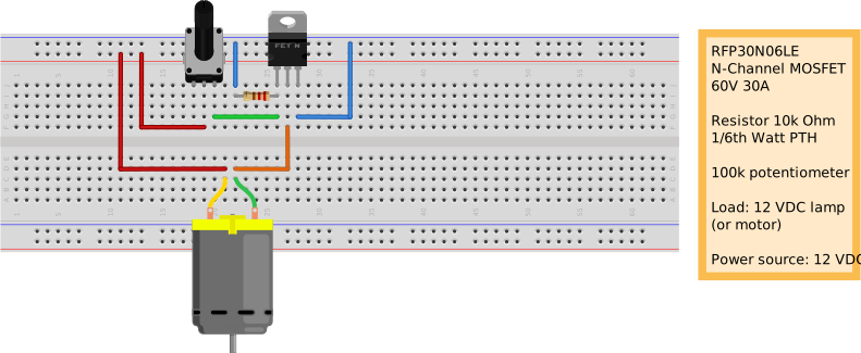
MOSFET controlled by a potentiometer
MOSFET controlled by PWM, version 1
Simple circuit to power DC load like a LED strip or a DC motor with a variable voltage.
The control signal comes from a GPIO pin on a Raspberry Pi.
Disclaimer: I'm a novice in electronics (and soldering obviously) and the circuit can be improved in many ways, any input are welcome.
Theory
There are lots of info and tutorials on these subjects on the internet but here are a quick walktrough.
A MOSFET are used to amplify the low-energy control signal to a usable current on the output. I use a n-type in this circuit so the power are regulated on the ground side.
The positive control signal comes from a GPIO pin on a Raspberry Pi controlled by a python script. The pin are configured as an output in PWM mode.
The R1 resistor works as a pull-down resistor, draining remaining voltage when the script are stopped. This can be skipped if you want to keep the last signal (for some time).
The R2 resistor works together with the capacitor as a low pass filter, flattening the short-term voltage variations in the control signal. This can be skipped but will then likely require higher PWM frequency to keep the load happy.
The LED strips I drive with this circuit are powered with 1 A at 12 VDC (0.25A each) from a separate power supply.
The ground on the Pi and the ground on the power supply should be wired together to get a common voltage reference level.
Test circuit
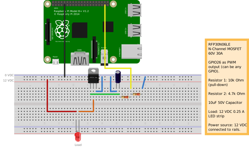
Board circuit
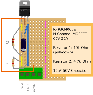
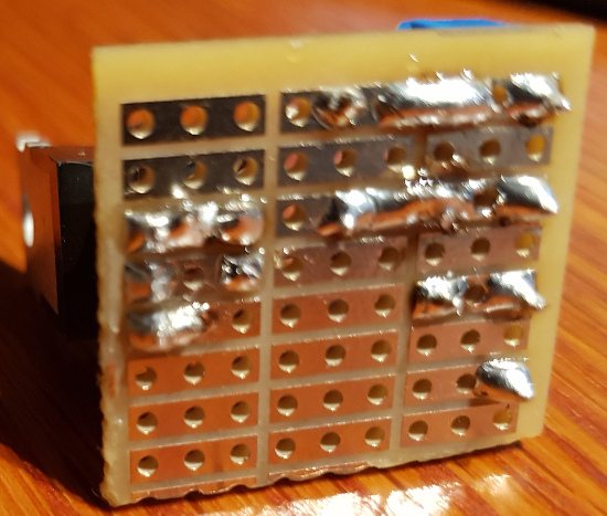
Soldered board
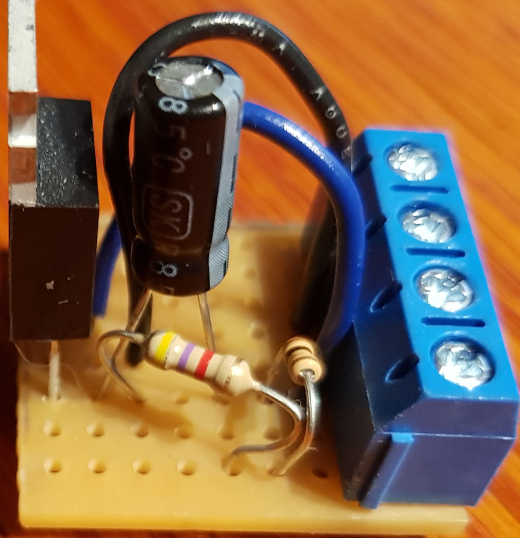
Notes
The featured parts are purchased from Lawicel and Kjell & Company. but can be found in many other places.
Problems with version 1
This circuit should only be used with a non-inductive load, like a LED, since I did not use a flywheel diode to handle the kickback from something like a coil or a DC motor.
The R2 resistor should have had a lower value and the capacitor should probably not have been used. The mosfet should have a distinct on/off-signal to move between states fast to avoid unnecessary heating. A capacitor on the output side might be useful to dampen the voltage variations.